
 EN
EN
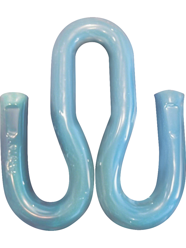
Selecting the right track clips for a specific rail fastening system is one of the most consequential decisions in any railway track construction or maintenance project. The wrong match can lead to rail instability, accelerated wear, noise issues, and even safety hazards. Engineers and procurement specialists working across heavy-haul freight, urban transit, and high-speed rail corridors all face the same fundamental challenge: fastening systems vary widely in design philosophy, load requirements, and component geometry, meaning that track clips cannot be selected arbitrarily or interchanged without careful technical validation.
This article provides a structured approach to matching track clips with specific rail fastening systems, covering the mechanical principles behind clip behavior, the classification of fastening systems and their clip requirements, and the key technical parameters that determine compatibility. Whether you are specifying components for a new line, replacing worn fasteners on an existing corridor, or adapting a proven system design to a new application environment, understanding how to correctly match track clips will help you avoid costly errors and deliver trackwork that performs reliably over its intended service life.
Understanding the Role of Track Clips in Rail Fastening Systems
What Track Clips Actually Do
Track clips are elastic spring components that apply a controlled, sustained clamping force to the foot of the rail, holding it securely against the baseplate or sleeper surface. Unlike rigid fasteners, elastic track clips work by deflecting under installation load and then recovering partially, maintaining a consistent toe load that resists rail uplift, longitudinal creep, and lateral displacement throughout the service cycle.
The elastic energy stored in a properly installed track clips is not incidental — it is the defining functional property. This stored energy compensates for rail vibration, thermal expansion and contraction, and the micro-movements introduced by repeated axle loading. A clip that is under-loaded will allow the rail to move more than the system design intends, while an over-loaded clip risks cracking the rail foot, damaging the insulator, or fatiguing the clip itself prematurely.
This is why matching track clips to a fastening system is not simply a matter of physical fit. It is fundamentally a matter of ensuring that the clip's spring stiffness, toe load, and deflection geometry are aligned with what the overall fastening system was engineered to deliver.
The Fastening System as an Integrated Assembly
A rail fastening system is an assembly of interdependent components: the rail itself, the baseplate or direct-fixation block, the insulating rail pad, the clip anchor (coach screw, bolt, or cast-in ferrule), and the track clips. Each component in the assembly is designed with specific tolerances and load-transfer expectations. When track clips are mismatched, they disrupt the load path through the entire assembly.
For example, when an elastic clip with a higher-than-specified toe load is installed into a system designed for a softer clip, the increased force on the rail foot insulator can cause insulator cracking or extrusion, reducing electrical isolation and accelerating deterioration. Conversely, a weaker clip installed in a heavy-haul application will fail to maintain adequate rail restraint under the high dynamic forces generated by heavy freight wagons.
Understanding the fastening system as a complete, integrated assembly is the necessary starting point before making any clip selection decision. The specifications for track clips within any given system are not arbitrary — they reflect the engineering balance struck across the entire assembly.
Classification of Rail Fastening Systems and Their Clip Requirements
Baseplate-Type Fastening Systems
Baseplate-type fastening systems, sometimes called indirect fastening systems, use a steel baseplate as an intermediary between the rail and the sleeper. The track clips in these systems clamp the rail to the baseplate rather than directly to the sleeper surface. This design distributes load across a larger area and provides a degree of angular adjustment that is useful in curved track alignments.
The clip selection in baseplate systems depends heavily on the geometry of the clip shoulder on the baseplate, the height and width of the clip anchor lugs, and the rail section being fastened. Different baseplate designs create different toe positions relative to the rail foot edge, which directly affects the lever arm of the clip and therefore the achievable toe load at a given clip deflection. Engineers must verify that the track clips being specified have a toe geometry that matches the baseplate's clip seating profile precisely.
Rail section compatibility is also critical. Heavier rail sections, such as 60 kg/m or UIC 60, have a wider and thicker rail foot than lighter sections like 50 kg/m, and this difference changes the effective contact point for the clip toe. A clip designed for one rail section will produce a different toe load and deflection when placed on a different section, even if it physically fits into the baseplate anchor.
Direct Fixation Fastening Systems
Direct fixation systems, commonly used on concrete sleepers and slab track, eliminate the baseplate by anchoring track clips directly into the sleeper or slab through a cast-in insert or an embedded anchor. These systems rely on precisely defined clip geometry to achieve the specified toe load, vertical stiffness, and electrical isolation performance required for the track design.
In direct fixation systems, the track clips often serve a dual function: providing the clamping force on the rail foot while simultaneously acting as the primary lateral restraint element. This means the clip's geometry must be validated not only for vertical toe load but also for lateral force capacity, which varies considerably between clip designs. Selecting a clip with insufficient lateral capacity in a direct fixation application can lead to rail gauge widening, particularly on curved track with high centrifugal loading.
The insulating rail pad in direct fixation systems also interacts with the track clips in ways that affect matching decisions. A softer pad will allow more rail head deflection under load, which changes the working angle of the clip and may shift the toe load below the intended design value. Engineers must consider the full pad-and-clip combination when specifying components for direct fixation applications.
Key Technical Parameters for Matching Track Clips
Toe Load and Spring Stiffness
Toe load — the vertical clamping force applied by the clip to the rail foot — is the most fundamental parameter in track clips selection. Each fastening system has a design toe load range, typically expressed in kilonewtons per rail seat, that ensures adequate rail retention without overloading the insulator or rail foot. Matching track clips correctly means confirming that the clip will deliver toe loads within this range across the expected range of installation torques and service wear states.
Spring stiffness, which describes how the toe load changes with clip deflection, is equally important. A stiffer clip will be more sensitive to installation variations and may produce excessive loads if components are not within their dimensional tolerances. A softer clip provides more tolerance to installation variability but may produce insufficient toe load if the rail pad compresses significantly under load. The specified stiffness must be matched to the overall compliance of the fastening assembly.
Test certificates for track clips should include load-deflection curves generated in accordance with the relevant international standard, such as EN 13481 or AREMA guidelines, confirming that the clip's measured performance falls within the system's specified envelope. Relying on dimensional fit alone, without verifying force-deflection behavior, is a common source of mismatched track clips in field installations.
Geometric Compatibility: Clip Profile, Anchor Spacing, and Rail Section
Beyond force characteristics, physical geometric compatibility is the most visible aspect of track clips matching. The clip must be able to seat correctly on its anchor, with the correct engagement depth and lateral position relative to the rail foot edge. Even small deviations in anchor spacing, clip leg length, or toe width can prevent proper seating and compromise the intended clamping geometry.
Different railway authorities have standardized specific clip profiles for their infrastructure, and these standards exist precisely because geometry determines performance. When sourcing replacement track clips, engineers should reference the original system drawing or the infrastructure manager's approved component list, not simply a physical comparison with a worn or damaged clip. Worn clips may have deformed geometries that are no longer representative of the correct specification.
Rail section compatibility must also be confirmed, as mentioned earlier. The clip toe must land on the upper surface of the rail foot within a defined distance from the foot edge. If the toe lands too close to the edge, it risks chipping the rail foot; too far inboard, and the effective toe load is reduced due to the shorter lever arm. This matching requirement ties clip selection directly to the rail section specification for each track zone.
Material Grade and Fatigue Performance
Track clips are typically manufactured from spring steel, and the specific material grade affects both the initial mechanical properties and the long-term fatigue life of the clip under cyclic loading. For high-traffic or high-speed applications, clips must demonstrate adequate fatigue resistance under millions of load cycles without significant loss of toe load. The material specification must therefore be matched to the traffic intensity of the application.
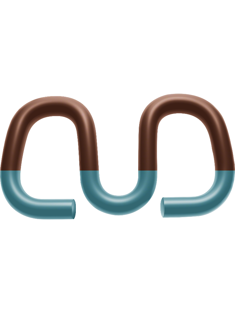
Corrosion resistance is another material consideration that intersects with system compatibility. Track clips used in coastal, tunnel, or chemically aggressive environments may require specific surface treatments or material grades to resist corrosion that could otherwise compromise the clip's spring properties over time. When matching track clips to a fastening system used in a demanding environment, the environmental exposure class should be factored into the material specification alongside the mechanical requirements.
Suppliers of track clips should be able to provide mill certificates, heat treatment records, and fatigue test data demonstrating compliance with the applicable standard. Procurement teams should request this documentation as a standard part of the approval process rather than relying solely on dimensional checks at incoming inspection.
Practical Steps for Verifying Clip-to-System Compatibility
Consulting System Documentation and Approved Component Lists
The most reliable starting point for matching track clips is the original fastening system documentation. This typically includes a system drawing showing the clip's nominal geometry, the anchor configuration, and the rail section it is designed for, along with a specification sheet defining the required toe load range, clip stiffness, and approved material grades. Most infrastructure managers maintain an approved component list that identifies specific clip variants accepted for use within their network.
When the original system documentation is not available, engineers can often obtain it from the system designer or the infrastructure manager's technical department. For legacy systems where documentation has been lost, physical reverse engineering combined with load-deflection testing of the existing clips can reconstruct the performance specification against which new track clips can be validated.
It is worth noting that many fastening systems have evolved through multiple generations, with updated clip designs that are geometrically similar but have modified performance characteristics. Engineers should verify not just the system family but the specific generation or variant when selecting replacement track clips.
Field Trial and In-Situ Verification
Even when track clips have been validated through documentation review and laboratory testing, a field trial on a representative section of track is a valuable final step before large-scale deployment. Field trials reveal installation issues, tool compatibility problems, and any unexpected interactions between the clip and the as-built track geometry that may not be apparent in a controlled laboratory setting.
During a field trial, installation torque should be measured and compared to the design specification, and the seating geometry of installed track clips should be inspected to confirm that the clip toe is contacting the rail foot at the correct position. Any clips that appear to be tilting, bridging, or not fully seating should be investigated before the system is cleared for wider use.
Post-installation toe load measurements, using calibrated clip gauges, can confirm that the installed track clips are delivering the expected clamping force. These measurements should be taken both immediately after installation and after a period of initial traffic loading, as some systems experience a small but predictable reduction in toe load during the bedding-in phase as mating surfaces conform to each other.
FAQ
Can track clips from one fastening system be used in a different system if they appear to fit?
Physical fit alone does not confirm compatibility. Track clips that appear to fit in a different system may produce incorrect toe loads, wrong deflection behavior, or inadequate lateral restraint, all of which can cause track geometry degradation or component damage over time. Always verify toe load, stiffness, and geometric parameters against the target system's specification before substituting clips between systems.
How often should track clips be inspected for wear or loss of toe load?
Inspection frequency for track clips depends on traffic volume, axle loads, and environmental conditions, but most infrastructure managers schedule visual inspections as part of routine track patrol and conduct formal toe load checks at periodic maintenance intervals, typically aligned with tamping or grinding cycles. Heavily trafficked corridors may require more frequent inspection of track clips than low-traffic branch lines.
What happens if track clips are installed with incorrect torque?
Under-torqued track clips will not achieve the specified toe load, leaving the rail under-clamped and vulnerable to longitudinal creep and uplift. Over-torqued clips risk cracking insulators, damaging rail foot surfaces, or introducing residual stresses in the clip that accelerate fatigue failure. Correct torque, validated during installation, is essential to achieving the intended performance of the fastening system.
Are track clips standardized internationally, or do specifications vary by country?
While there are internationally recognized test standards such as EN 13481 that define how track clips should be tested, there is no single universal clip specification. Different railway networks use different fastening systems, and each system has its own clip geometry and performance requirements. Engineers working on international projects must identify the specific fastening system approved for the target network and source track clips validated to that system's requirements rather than assuming international interchangeability.
Table of Contents
- Understanding the Role of Track Clips in Rail Fastening Systems
- Classification of Rail Fastening Systems and Their Clip Requirements
- Key Technical Parameters for Matching Track Clips
- Practical Steps for Verifying Clip-to-System Compatibility
-
FAQ
- Can track clips from one fastening system be used in a different system if they appear to fit?
- How often should track clips be inspected for wear or loss of toe load?
- What happens if track clips are installed with incorrect torque?
- Are track clips standardized internationally, or do specifications vary by country?